- Overview
- Product Description
- Product Parameters
- Detailed Photos
Basic Info.
Product Description
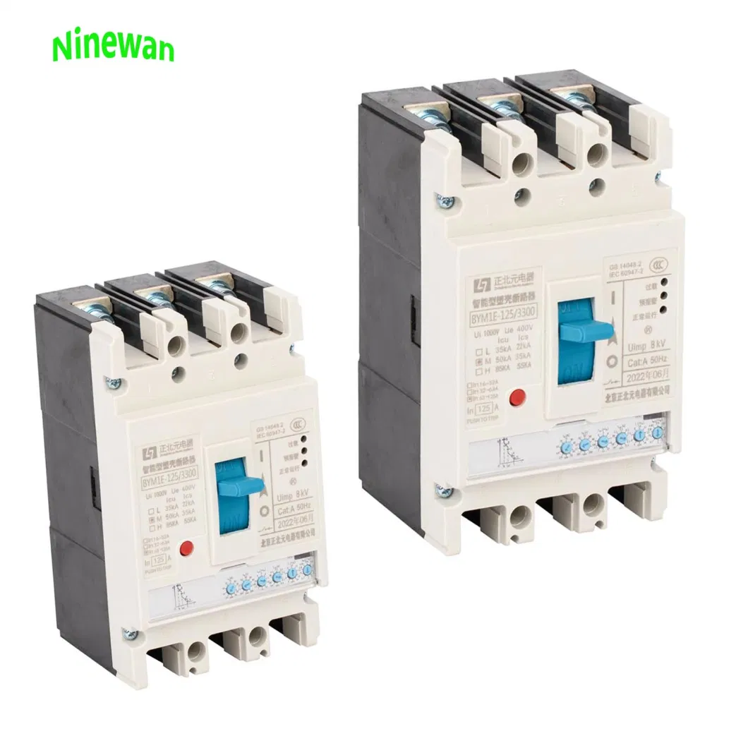
400V MCCB breaker 16~160A Compact DIN Rail Molded Case Circuit Breaker MCCB
Standard:
circuit breaker and auxiliaries comply with the following international standard:
1.IEC/EN 60947-1
Low-voltage switchgear and controlgear-part 1: General rules;
2.IEC/EN 60947-2
Low-voltage switchgear and controlgear-part 2: Circuit breakers;
MCCB(Standard use environment for MCCB)
1. Ambient temperature: Within the range of -5ºC--+55ºC(However, when the temperature exceed 40ºC,it should be considered to reduce the capacity to use);
2. Relative humidity: Within the range of 45%--85%;
3. Altitude: 2000m or less(However, if it exceeds 1000m, atmosphere correction through humidity test and withstand voltage test can be considered);
4. Atmosphere where excessive steam, oil steam, smoke, dust, salt and other corrosive materials do not exist;
Classification:
According to the poles: 2-poles, 3-poles
According to the rated current: Fix type
| Thermal-Magnetic fixed type Circuit Breakers | ||||
| Model | XHM1-125 | |||
| Breaking Capacity Code | L | M | ||
| Rated Current of Frame size- Inm (A) | 125 | |||
| Rated Current-In(40,50 or 55ºC) (A) | 10- 12,5-16-20 - 25 - 32 - 40 - 50 - 63 A | |||
| Rated İnsulation Voltage -Ui(a.c.) 50-60Hz (V) | 500 | |||
| Rated operation Voltage -Ue(a.c.) 50-60Hz (V) | 400 | |||
| Number of Pole | 3P / 4P | |||
| Rated ultimate short Circuit breaking Capacity kA Icu AC400V/50Hz O-CO (KA) | 25 | 50 | ||
| Rated service short Circuit breaking Capacity kA Ics AC400V/50Hz O-CO-CO (KA) | 18 | 35 | ||
| Rated short-circuit breaking capacity Icm(peak)/cos ф AC400V/50HZ O-CO (KA) | 41/0.3 | 73.5/0.25 | ||
| Rated impulse withstand Voltage -Uimp (V) | 8000 | |||
| Dielectric Propery (V) | 3000 | |||
| lonization distance (mm) | ≤30/0 | |||
| Endurance | Total Cycles | 8000 | ||
| Electrical Life | 6000 | |||
| Mechanical Life | 8500 | |||
| Over Current trip | Thermal and Magnetic release fix type | √ | ||
| Category (EN 14048.2/IEC 60947-2) | Main circuit | A/0 | ||
| Auxiliary circuit | AC-15 | |||
| Under Voltage Release | √ | |||
| Shunt Release | √ | |||
| Auxiliary Contact | √ | |||
| Alarm Contact | √ | |||
| Auxiliary Contact and Alarm Contact | √ | |||
| Handle Operation Mechanism | √ | |||
| Electrical Operastion Mechanism | √ | |||
| Terminal cover | √ | |||
| Phase seperator | √ | |||
| Extention Handle | - | |||
| W (mm) | 3P | 78 | ||
| 4P | 103 | |||
| L (mm) | 3P | 135 | ||
| 4P | 135 | |||
| H (mm) | 3P | 73.5 | ||
| 4P | 73.5 | |||
| Weight | Fixed version 3P/4P | 1.2/1.6 | ||
| Plug-in version 3P/4P | 1.4/1.8 | |||
| Draw out version 3P/4P | - | |||


